Quality Control and Acceptance Testing
Rigorous quality control and acceptance testing ensure that the installed system meets all design specifications and performance requirements. This chapter outlines quality control procedures during installation and comprehensive acceptance testing protocols.
10.1 Quality Control During Installation
Quality control must be implemented throughout the installation process to prevent defects and ensure compliance with specifications. A structured quality control program includes inspection checklists, hold points requiring approval before proceeding, and documentation of all inspections and tests.
10.1.1 Pre-Installation Inspections
Before installation begins, verify that all equipment has been received and inspected for shipping damage, review shop drawings and submittals for compliance with specifications, confirm that installation site is ready (power, access, clearances), and verify that all required tools and materials are available.
10.1.2 Installation Quality Checkpoints
Critical installation checkpoints include equipment mounting and leveling verification, ductwork pressure testing for air leakage, electrical connections torque verification and insulation testing, control wiring continuity and labeling verification, and sensor calibration and placement verification.
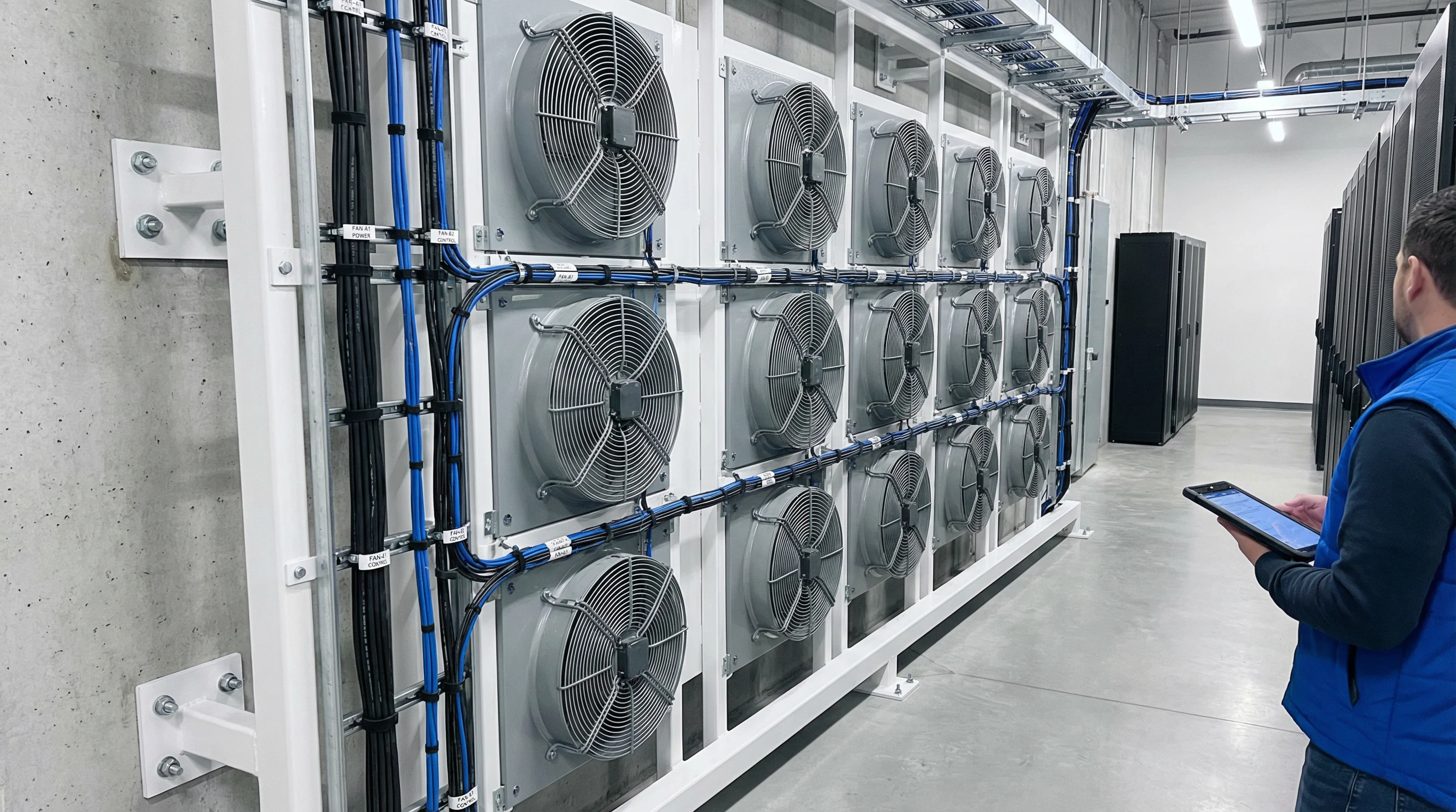
Figure 10.1: Example of Professional Installation with Proper Alignment and Cable Management
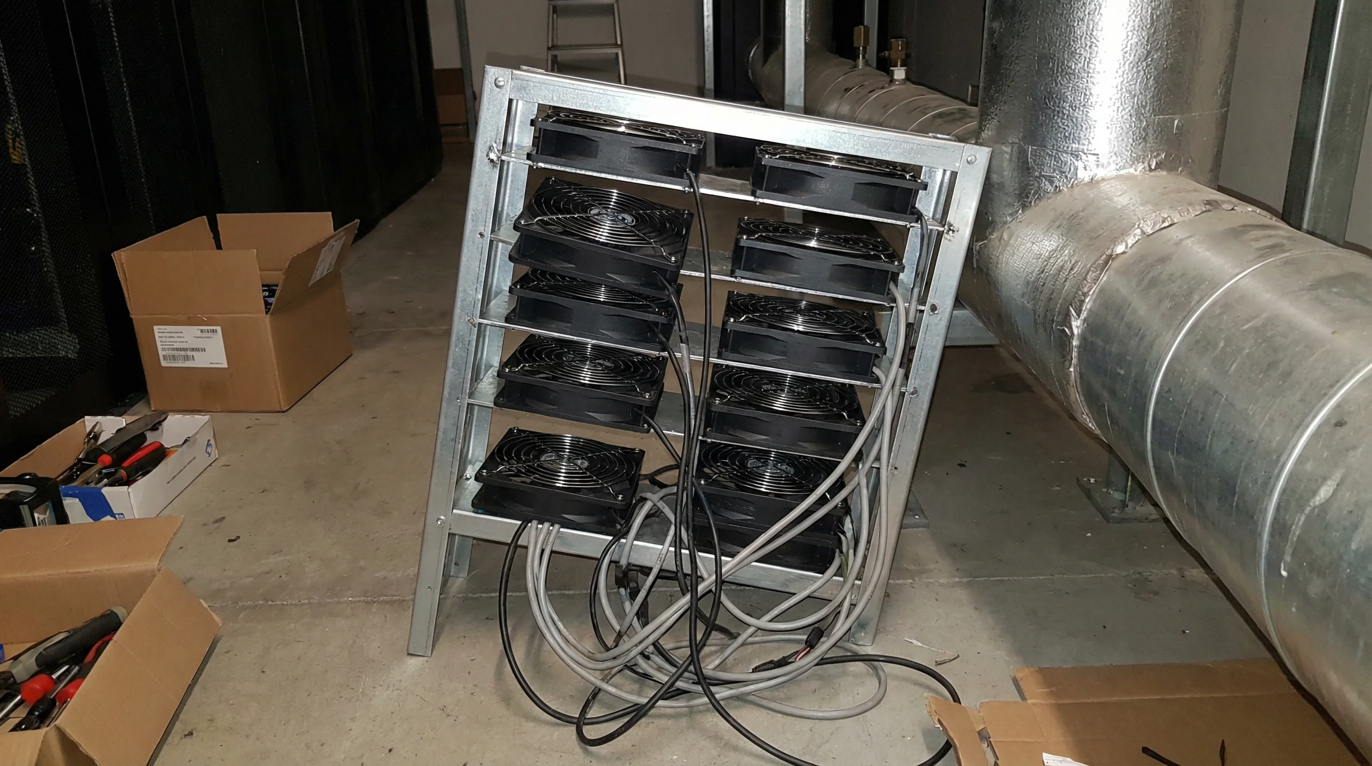
Figure 10.2: Example of Poor Installation Showing Common Defects to Avoid
10.2 Functional Testing
Functional testing verifies that all system components operate correctly individually and as an integrated system. Testing should follow a systematic sequence from individual components to full system operation.
10.2.1 Component-Level Testing
Component-level testing includes verifying fan operation at various speeds and measuring airflow and power consumption, testing damper operation through full range of motion and verifying position feedback, testing compressor operation and measuring cooling capacity, and verifying sensor accuracy against calibrated reference instruments.
10.2.2 System-Level Testing
System-level testing includes verifying control sequences under various operating modes, testing automatic failover to backup equipment, verifying alarm and notification functions, and testing integration with BMS and fire alarm systems.
10.3 Performance Testing
Performance testing verifies that the system meets all specified performance criteria including cooling capacity, energy efficiency, and environmental control accuracy.
10.3.1 Cooling Capacity Verification
Cooling capacity is verified by measuring airflow rate and temperature rise across IT equipment, calculating total cooling capacity using the formula Q = ρ × Cp × V × ΔT, comparing measured capacity against design specifications (typically ±10% tolerance), and documenting results with calibrated instruments.
10.3.2 Energy Efficiency Verification
Energy efficiency is verified by measuring total system power consumption under various load conditions, calculating PUE (Power Usage Effectiveness) as Total Facility Power / IT Equipment Power, comparing measured PUE against design targets, and identifying opportunities for optimization if targets are not met.
10.3.3 Environmental Control Accuracy
Environmental control accuracy is verified by monitoring temperature and humidity at multiple locations over 24-48 hour period, verifying that all measurements remain within specified tolerances (typically ±1°C, ±5% RH), identifying and correcting any hot spots or areas of poor control, and documenting environmental uniformity across the data center.
10.4 Acceptance Criteria and Documentation
Clear acceptance criteria must be established before testing begins. All test results must be documented and reviewed against acceptance criteria.
| Test Category | Acceptance Criteria | Test Method | Documentation Required |
|---|---|---|---|
| Cooling Capacity | ≥100% of design load | Airflow and temperature measurement | Test report with calculations |
| Temperature Control | ±1°C of setpoint | 24-hour monitoring at multiple points | Temperature trend charts |
| Humidity Control | ±5% RH of setpoint | 24-hour monitoring | Humidity trend charts |
| Airflow Distribution | Within ±15% of design | Traverse measurements | Airflow measurement report |
| Energy Efficiency | PUE ≤ design target | Power measurement and calculation | PUE calculation report |
| Control Functions | All sequences operate correctly | Functional testing | Functional test checklist |
| Safety Systems | All interlocks function correctly | Simulated alarm testing | Safety system test report |
10.5 Deficiency Management
Any deficiencies identified during testing must be documented, corrected, and retested. A formal deficiency tracking system should be used to ensure all issues are resolved before final acceptance.
10.5.1 Deficiency Classification
Deficiencies are classified by severity: Critical deficiencies prevent system operation or pose safety hazards and must be corrected immediately. Major deficiencies significantly impact performance or reliability and must be corrected before acceptance. Minor deficiencies have minimal impact and may be corrected after acceptance with an agreed schedule.
10.5.2 Retest Procedures
After deficiency correction, affected tests must be repeated to verify proper operation. Retest scope depends on the nature of the deficiency and may range from repeating a single component test to full system performance testing.