Equipment Selection and Interface Design
Proper equipment selection and interface design ensure system compatibility, performance, and long-term reliability. This chapter provides detailed selection criteria and interface specifications for all major system components.
5.1 Air Handling Unit Selection
Air Handling Units (AHUs) are selected based on airflow capacity, pressure capability, filtration requirements, and energy efficiency. Key selection parameters include airflow rate (m³/h), external static pressure (Pa), filter grades and pressure drop, cooling coil capacity (kW), and fan motor efficiency.
5.1.1 Sizing Criteria
AHU capacity is determined by the total cooling load and required air changes per hour. For data centers, a minimum of 20-30 air changes per hour is recommended to ensure adequate air circulation. The formula is: AHU Capacity (m³/h) = Room Volume (m³) × Air Changes per Hour. Multiple smaller units are preferred over a single large unit to provide redundancy and operational flexibility.
5.1.2 Energy Efficiency Considerations
High-efficiency EC (Electronically Commutated) fans should be specified with motor efficiency >90% and variable speed control. Low face velocity through filters and coils (2.0-2.5 m/s) minimizes pressure drop and fan energy. Heat recovery options such as rotary heat exchangers or run-around coils can further improve energy efficiency in extreme climates.
5.2 Precision Air Conditioner Selection
Precision air conditioners provide close control of temperature and humidity with high reliability and efficiency. Selection criteria include cooling capacity (kW), sensible heat ratio (SHR), energy efficiency ratio (EER), and redundancy configuration.
| Parameter | Specification Range | Recommended Value | Notes |
|---|---|---|---|
| Cooling Capacity | 20-500 kW per unit | 50-150 kW per unit | Multiple smaller units provide better redundancy |
| Sensible Heat Ratio | 0.85-0.98 | >0.95 | Data centers have high sensible loads |
| Energy Efficiency Ratio | 2.5-4.0 | >3.5 | Higher EER reduces operational costs |
| Control Accuracy | ±0.5-2°C | ±1°C | Tighter control for critical applications |
5.3 Sensor Selection and Placement
Accurate and reliable sensors are essential for effective control. Sensor selection must consider accuracy, response time, output signal type, and environmental rating.
5.3.1 Temperature and Humidity Sensors
High-precision digital sensors with ±0.3°C temperature accuracy and ±2% RH humidity accuracy are recommended. Sensors should have response times under 30 seconds and provide digital output (Modbus RTU or 4-20mA) for direct integration with controllers. Placement locations include outdoor air intake, supply air duct, cold aisle (at multiple heights), hot aisle, and return air path.
5.3.2 Pressure Sensors
Differential pressure sensors monitor filter loading, damper position verification, and aisle containment effectiveness. Sensors should have 0-500 Pa range with ±1% full-scale accuracy. Critical measurement points include across each filter bank, across dampers, and between cold aisle and hot aisle.
5.4 Control Interface Specifications
Standardized interfaces ensure interoperability between equipment from different manufacturers and facilitate integration with building management systems.
5.4.1 Communication Protocols
The system should support multiple standard protocols including Modbus TCP/RTU for general equipment control, BACnet IP for building automation integration, SNMP for network management, and OPC UA for SCADA integration. All communication should use industrial-grade network equipment with redundant ring topology.
5.4.2 Electrical Interfaces
Control signals use standard voltage levels: 24VDC for digital I/O, 4-20mA or 0-10VDC for analog signals, and 230VAC or 400VAC for power distribution. All control wiring should be shielded and separated from power cables to minimize electromagnetic interference.
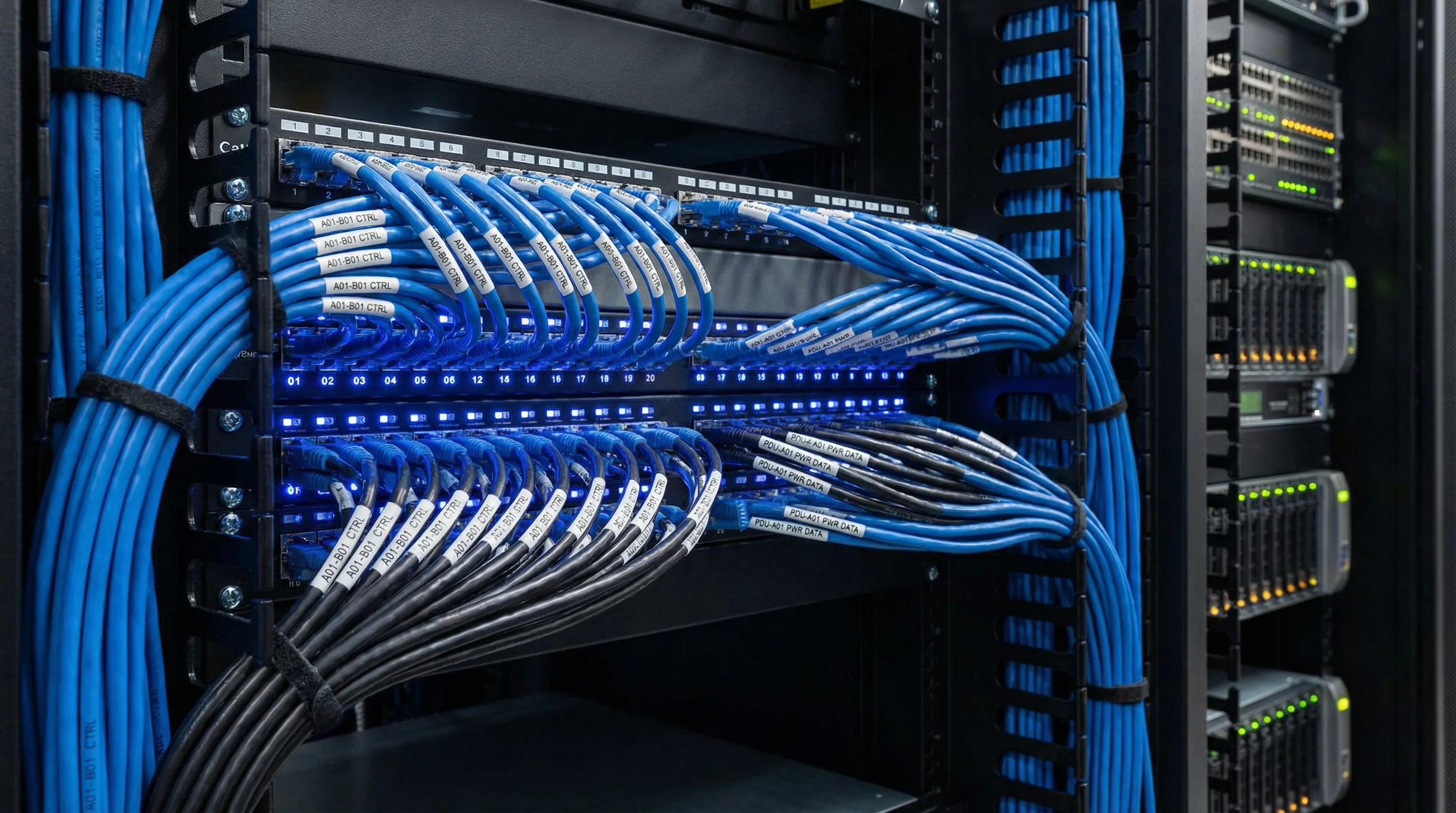
Figure 5.1: Professional Network and Control Cabling Installation