Safety and Risk Management
Safety and risk management are paramount in data center operations. This chapter addresses electrical safety, fire protection, emergency response, and risk mitigation strategies to ensure personnel safety and equipment protection.
6.1 Electrical Safety
Electrical safety encompasses proper grounding, overcurrent protection, arc flash mitigation, and lockout/tagout procedures. All electrical work must comply with local electrical codes and international standards such as IEC 60364 or NEC (National Electrical Code).
6.1.1 Grounding and Bonding
A comprehensive grounding system protects personnel and equipment from electrical faults and lightning strikes. The system includes a main grounding electrode connected to building steel and foundation, equipment grounding conductors connecting all metal enclosures, isolated ground system for sensitive electronic equipment, and lightning protection system with surge protective devices (SPDs) at service entrance and distribution panels.
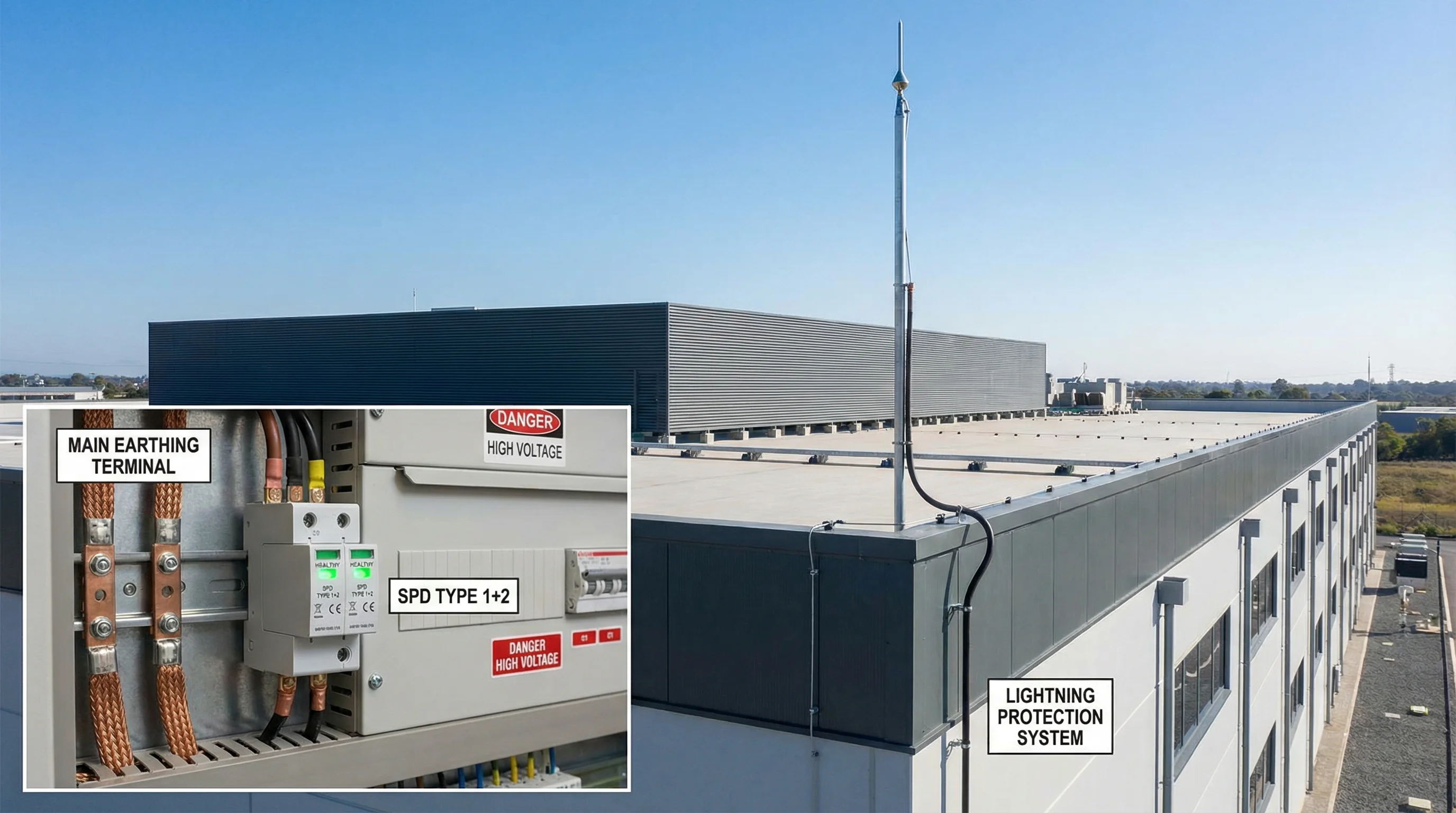
Figure 6.1: Grounding System and Lightning Protection Installation
6.1.2 Overcurrent Protection
Properly sized circuit breakers and fuses protect wiring and equipment from overload and short-circuit conditions. Protection devices must be coordinated to ensure selective tripping, where only the breaker closest to the fault opens, minimizing disruption to unaffected circuits.
6.1.3 Arc Flash Hazard Mitigation
Arc flash incidents can cause severe injury or death. Mitigation strategies include arc flash hazard analysis and labeling of all electrical equipment, use of arc-resistant switchgear in high-energy locations, implementation of arc flash detection and rapid shutdown systems, and mandatory personal protective equipment (PPE) for electrical work based on hazard level.
6.2 Fire Protection Integration
The cooling system must integrate seamlessly with the facility's fire protection system to ensure safe shutdown during fire events while minimizing damage to IT equipment.
6.2.1 Fire Alarm Linkage
The cooling system control receives fire alarm signals through hardwired relay contacts or network communication. Upon receiving a fire alarm, the system executes predefined shutdown sequences including closing outdoor air dampers to prevent smoke ingress, stopping supply fans to eliminate oxygen supply, maintaining exhaust fans to assist smoke evacuation, and shutting down mechanical cooling equipment.
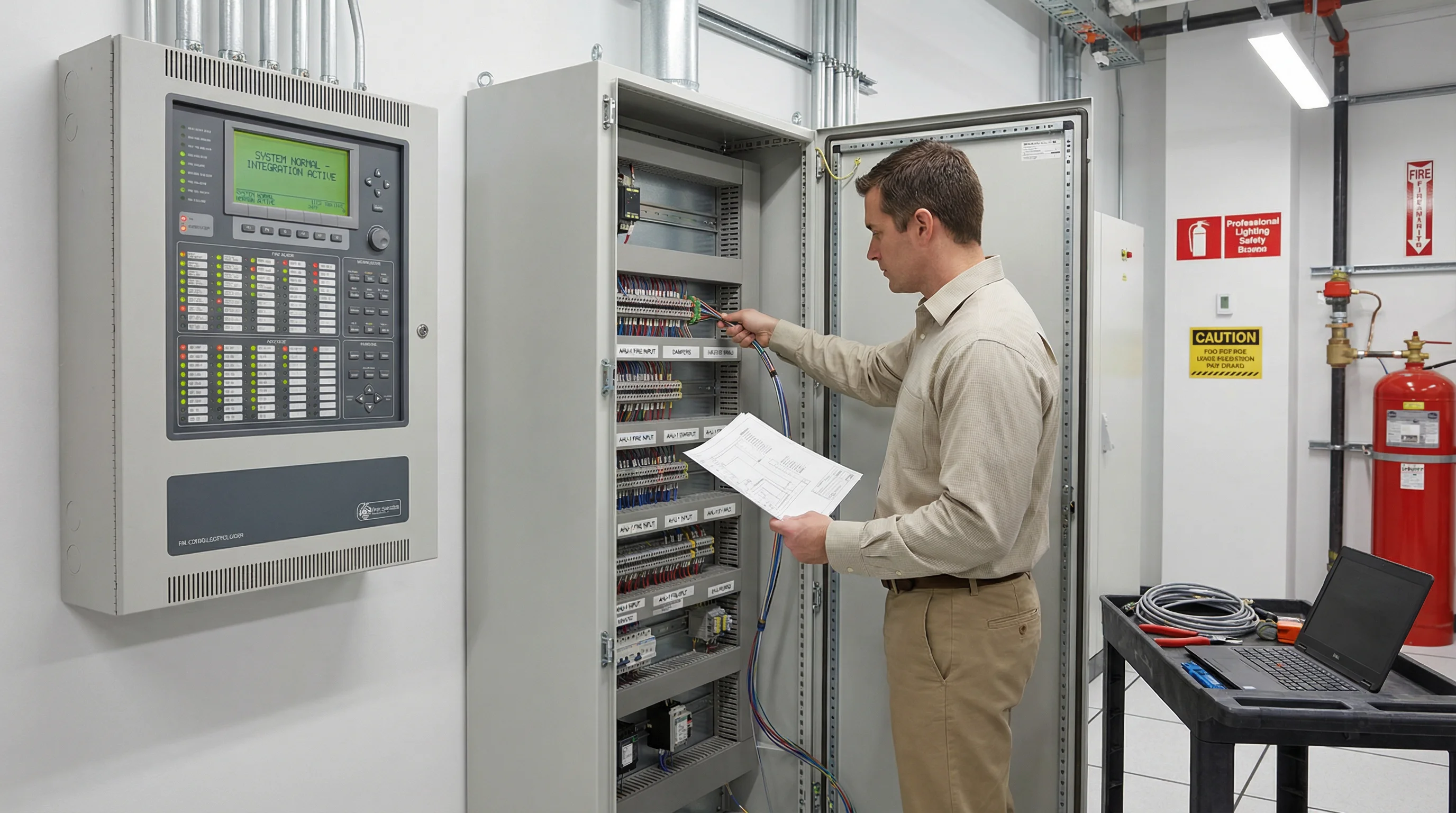
Figure 6.2: Fire Alarm Control Panel Integration with HVAC System
6.2.2 Smoke Detection and Response
Very Early Smoke Detection Apparatus (VESDA) or similar aspirating smoke detection systems provide the earliest possible warning of fire conditions. The cooling system can respond to different alarm levels with staged responses: Alert level triggers increased monitoring and notification, Action level initiates controlled shutdown of affected zones, and Fire level executes full emergency shutdown and activates suppression systems.
6.3 Emergency Response Procedures
Documented emergency response procedures ensure rapid and effective action during critical events. Procedures must be regularly reviewed, updated, and practiced through drills.
6.3.1 System Failure Response
In the event of cooling system failure, immediate actions include activating backup cooling units (if available), increasing airflow from remaining operational units, raising temperature setpoints to extend available cooling capacity, implementing emergency load shedding to reduce heat generation, and notifying management and technical support.
6.3.2 Emergency Shutdown Procedures
Emergency shutdown may be required for fire, flooding, or severe equipment malfunction. The procedure includes activating emergency stop (E-stop) buttons located at exits and control room, verifying that all motorized equipment has stopped, closing main electrical disconnects if safe to do so, and documenting the event and all actions taken.
6.4 Risk Assessment and Mitigation
Systematic risk assessment identifies potential failure modes and implements appropriate mitigation measures. The process follows a structured methodology such as Failure Mode and Effects Analysis (FMEA).
| Risk Category | Potential Failure | Impact | Mitigation Strategy |
|---|---|---|---|
| Equipment Failure | Compressor failure | Loss of cooling capacity | N+1 redundancy, preventive maintenance |
| Control System | Controller malfunction | Loss of automatic control | Dual redundant controllers, manual override |
| Power Supply | Utility power outage | System shutdown | UPS backup for controls, generator for full system |
| Sensor Failure | Temperature sensor drift | Incorrect control decisions | Multiple sensors with voting logic, regular calibration |
| Human Error | Incorrect setpoint change | Environmental excursion | Access control, change management procedures |