System Architecture Design
The architecture design phase translates conceptual requirements into detailed technical specifications. This chapter covers the key architectural decisions that determine system performance, reliability, and maintainability.
4.1 Cooling Topology Selection
The cooling topology defines how cooling capacity is distributed throughout the data center. The three primary topologies are room-level cooling, row-level cooling, and rack-level cooling, each with distinct advantages and trade-offs.
4.1.1 Room-Level Cooling
Room-level cooling uses perimeter-mounted Computer Room Air Conditioning (CRAC) or Computer Room Air Handler (CRAH) units to cool the entire data center space. This traditional approach is suitable for low to medium power densities (2-6 kW per cabinet) and provides simple design and operation. However, it suffers from inefficient air distribution, potential hot spots in high-density areas, and high fan energy consumption due to long air travel distances.
4.1.2 Row-Level Cooling
Row-level cooling places cooling units directly within server rows, providing close-coupled cooling with short air paths. This approach is ideal for medium to high power densities (5-15 kW per cabinet) and offers improved efficiency through reduced air travel distance, better temperature uniformity, and easier capacity scaling. In-row units are typically installed between cabinets or at row ends.
4.1.3 Rack-Level Cooling
Rack-level cooling integrates cooling directly into individual cabinets or uses rear-door heat exchangers. This approach handles very high power densities (>15 kW per cabinet) and provides maximum cooling efficiency. However, it requires higher capital investment and more complex maintenance procedures.
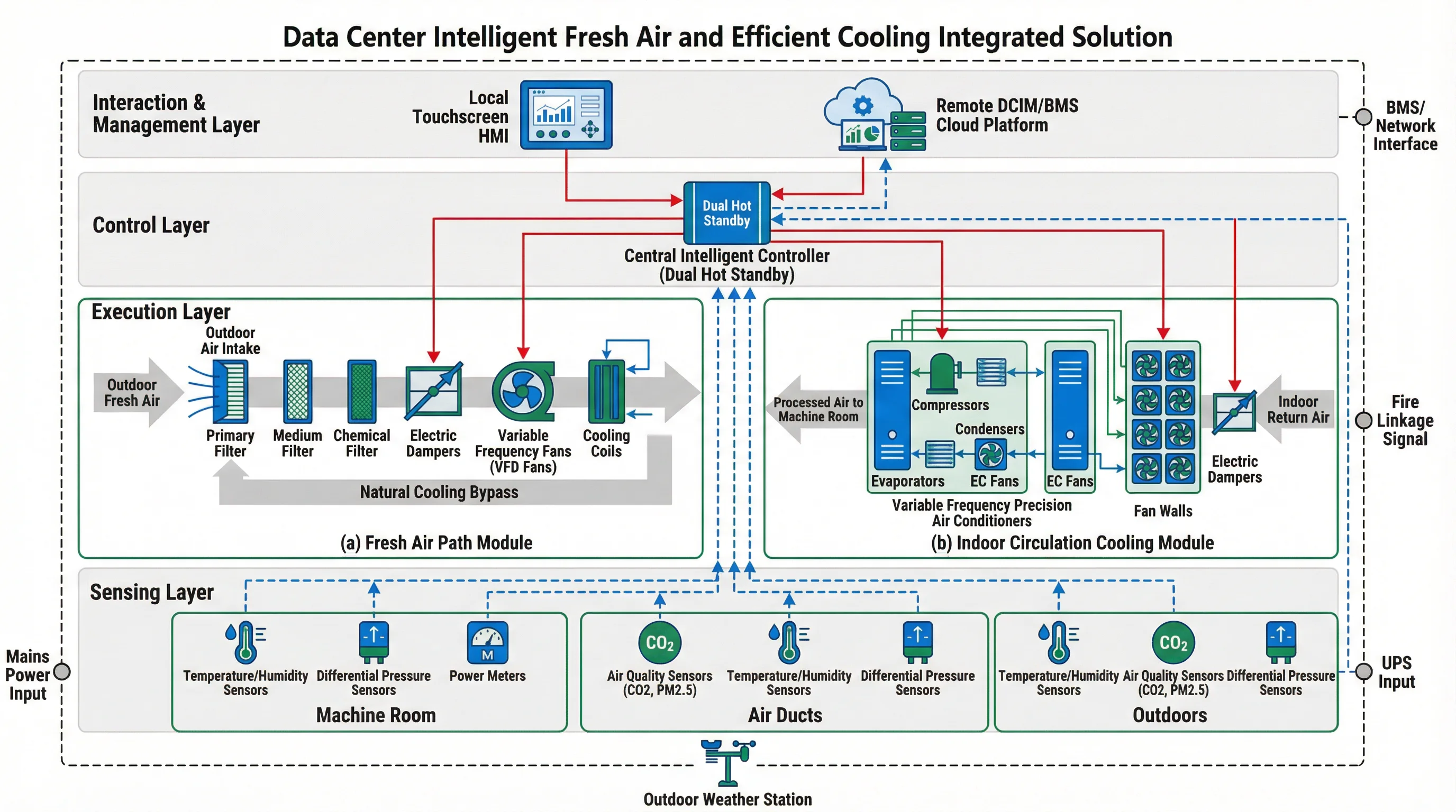
Figure 4.1: Complete System Architecture Showing All Layers and Interconnections
4.2 Airflow Management Design
Effective airflow management is critical for preventing hot spots, minimizing bypass airflow, and reducing fan energy consumption. The key strategies include aisle containment, raised floor vs. overhead distribution, and proper sealing of air leakage paths.
4.2.1 Hot Aisle vs. Cold Aisle Containment
Aisle containment physically separates hot and cold air streams to prevent mixing. Cold Aisle Containment (CAC) encloses the cold aisle with doors and ceiling panels, creating a pressurized cold air plenum. Hot Aisle Containment (HAC) encloses the hot aisle, capturing hot exhaust air for efficient return to cooling units. HAC is generally preferred for high-density environments as it prevents hot air from escaping into the room and allows higher return air temperatures.
4.2.2 Raised Floor Distribution
Raised floor systems use the underfloor plenum as a cold air distribution pathway. Perforated floor tiles in cold aisles deliver conditioned air directly to equipment intakes. This approach provides flexible air delivery locations and accommodates cable routing, but requires careful pressure balancing to ensure uniform airflow distribution.
4.2.3 Overhead Distribution
Overhead distribution systems use ceiling-mounted ductwork to deliver cold air from above. This approach is common in retrofit projects where raised floors are not feasible and in high-density deployments where underfloor space is insufficient. Overhead systems require careful duct design to minimize pressure drop and ensure even distribution.
4.3 Redundancy Architecture
Redundancy architecture determines system availability and fault tolerance. The architecture must balance reliability requirements against capital and operational costs.
| Component | N Configuration | N+1 Configuration | 2N Configuration |
|---|---|---|---|
| Air Handling Units | Minimum required capacity | One additional unit | Fully redundant parallel systems |
| Precision AC Units | Minimum required capacity | One additional unit | Two independent systems |
| Control Systems | Single controller | Hot standby controller | Fully independent control systems |
| Power Distribution | Single feed | Dual feed with automatic transfer | Fully redundant power paths |
4.4 Control System Architecture
The control system architecture defines how sensors, controllers, and actuators are interconnected and how control decisions are made. Modern systems use hierarchical control with local autonomous controllers coordinated by a central supervisory system.
4.4.1 Centralized vs. Distributed Control
Centralized control uses a single master controller to manage all system components. This approach provides unified optimization and simplified programming but creates a single point of failure. Distributed control uses multiple autonomous controllers that can operate independently. This approach provides better fault tolerance and scalability but requires more complex coordination logic.
4.4.2 Communication Architecture
The communication network connects all control devices and provides data exchange with upper-level management systems. Industrial Ethernet with redundant ring topology is the preferred architecture, providing high bandwidth, deterministic communication, and automatic failover. Standard protocols include Modbus TCP, BACnet IP, and OPC UA for interoperability with diverse equipment.